Our solution
- The complexity of the hardware must be proportionate to the needs of the system, without unnecessary redundancies in order to maximize its reliability (no PLC nor PC)
- Each unit of the system (single fin control, stabilization control, command and monitoring stations) must have its own operational autonomy so as to be able to intervene automatically in case of failure of one of the other units, and operate in degraded system condition or secure the system (housing fins).
- Communication between various units must be simple, functional and reliable.
- Wiring among units must be minimal and without the need for special cables
To achieve this purpose, the system is based on very few boards specifically designed, with the minimum of components required, each with its own microprocessor for managing the functions of the unit to which they belong. Communication among boards takes place via a serial line (CAN bus and RS232) at low speed, to optimize the transmission quality even in disturbed environments.
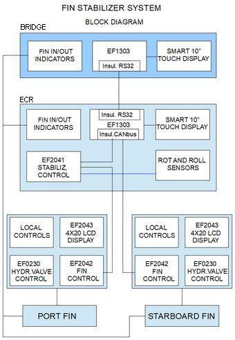
All control components are shown in the block diagram, where the EFxxxx codes refer to the electronic boards.
Description
The system layout is function of the original layout of the system to be refitted. A typical
configuration is as follows.
Fin room
- Fin control board EF2042, for the complete management of the fin operations
- Control board of the hydraulic power unit (HPU) EF0230.
- Relays to control pump and hydraulic valves.
- Front panel with switches and indicators for local control of the fin.
- 4-line, 20-character LCD display to monitor fin status and angle, control status and alarms and 4 buttons to change control parameters.
ECR
- Roll speed sensor (gyro)
- Inclinometer (EF1933 board plugged into the EF2041 main board)
- Main control board EF2041, that is the core of the system, making all calculation for the stabilization.
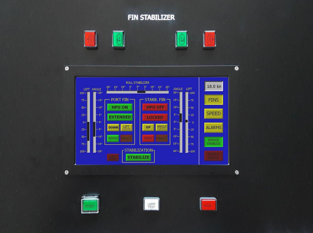
- 10 ”touch screen display for system monitoring controlled by the EF1303 board.
- Start and Stop button to start or stop stabilization.
- Lights to indicate the status of the fins, inside or out, according to SOLAS regulations
Bridge
- A replica of the ECR panel, with very few differences such as: brightness control, speed acquisition from log and GPS (NMEA).
Summmary of operating procedures
Normal operation
The bridge control is enabled/disabled by two buttons on the main page of the touch screen display in ECR
Only two buttons, START and STOP, are needed to activate the whole sequence of operations up to the start of stabilization, or to start the sequence to house the fins and stop the system.
Local control
Setting the switch in the fin control panel to LOCAL it is possible to manually start/stop the hydraulic pump and to move the fin out and back in.
The fin angle can be controlled locally, with a potentiometer, setting the EF2042 switch to LOCAL.
Speed setting
Ship speed is normally given by log (speed over water) and GPS (speed over ground). The operator can select the speed source (log, GPS, manual) on the display, but validity checks are performed automatically and, in case of failure of the selected source, the source is automatically changed, with priority to the log and subsequently to the GPS.
Alarms
See the figure “ALARMS page” where the alarms are listed. The list of alarms may vary depending on the system.
When the alarms are activated, the ALARMS page is automatically selected.
Some alarms, low oil pressure and maximum fin angle, generate an immediate stop of the pump and put the fin in a locked state. The lock must be reset on the touch screen display in ECR.
DISPLAY in ECR and Bridge
The following three pages can be selected on the ECR and bridge displays (an example relevant to the refitting of a Sperry system with lift control):
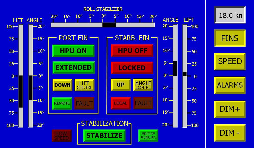
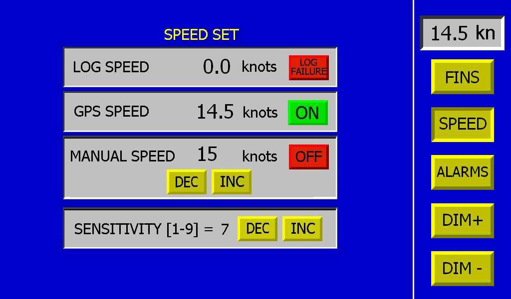
It is possible to select the source to be used using the relevant buttons.
If the ship speed is less than 5 knots the system will not start and, if running, will stop stabilization and initiate the system shutdown sequence.
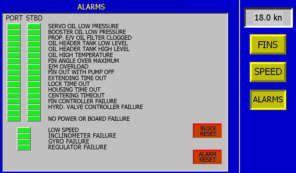
The alarm list may vary according to the specific system.
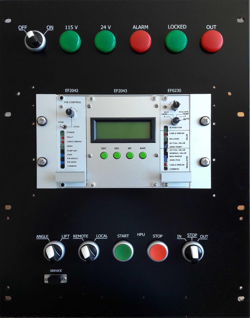
The panel in the figure is typical for the refitting of some Sperry systems, but can vary considerably depending on the pre-existing system.
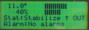
A small LCD display provides all the information on the operation of the fin control, and give the possibility to set some parameters.